NRQ-62
The Ultimate Regenerative Receiver
by Jim Stoneback K4XAF
When I first encountered “the ultimate regen” in the pages of Electric Radio Magazine, I decided immediately that I must build one of my own. The article, by Bruce Vaughan NR5Q, was the first in a series of three, appearing in consecutive issues of ER Mag, December 2001 thru February 2002 (vols. 51 - 53).
Even so, 18 months passed before I was able to start building my receiver. During that time I did collect some of the parts I would need to complete the project. From Ebay I acquired an old Army surplus VHF signal generator which yielded a power transformer and choke needed for the 350 vdc power supply and the 6V6 audio output tube I would need. Also from Ebay came the National PW dial and gearbox used in the receiver.
Bruce had built two of these receivers just to verify that the excellent performance of the first one wasn’t a fluke. I built mine as much like his as was possible, with heavy emphasis on solid physical construction. The 1/8” front panel, the 3/16” chassis and panel-to-chassis braces came from Charles Byers who sells them as kits – precut and prebent requiring the user to drill holes and bolt it together using user-supplied hardware.
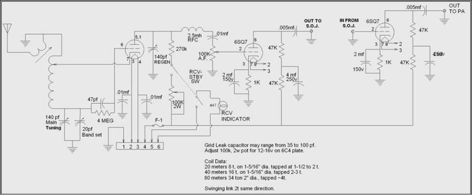
The receiver is very simple: A regenerative detector followed by a two-stage audio preamp ending with a 6V6 audio output tube. I’ve reproduced the schematic in two parts just as they appeared in ER. The receiver is also built on two chassis – the audio output, selectoject and power supply on one chassis; the detector and audio preamp on the other.
Figure 1. Regenerative detector and audio pre-amp
The detector is a 6C4 and works really well with the plate voltage down around 12-15 vdc. The coil forms are pieces of 1” PVC pipe cut 1.5” to 3” in length or pill bottles of similar length and epoxied onto octal sockets purchased from Antique Electronic Supply. Windings can be close- or wide-spaced. I’ve wound additional coils for continuous coverage from 2.4 to 19 MHz. I’ve also wound a coil for the AM broadcast band and plan another to cover 160 m. That would yield continuous coverage from 540 kHz to 19 mHz. I’m currently experimenting with coils for the 20 to 30 MHz range. The link coil is a couple of turns of #14 bare wire held by a ¼” delrine rod (spruce works, too!) which is turned by a National Velvet Vernier allowing fine adjustment of the position of the link over the coil (the vernier isn’t really necessary – I just used it because I had an extra one).
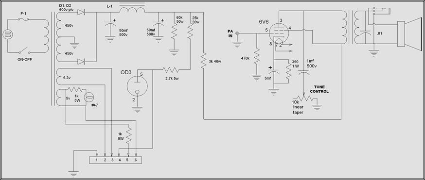
Figure 2. Power supply and audio output
As you can see from the schematic, this receiver drives a speaker. Boy does it ever! If you’ve ever heard a National HRO-50, HRO-60, NC-173, or NC-183, you know what this regen receiver sounds like – warm, room-filling audio. It is as sensitive as most modern receivers and selective enough for listening to AM or shortwave broadcasting. For CW use, I have to engage the narrow-band filter between my ears.
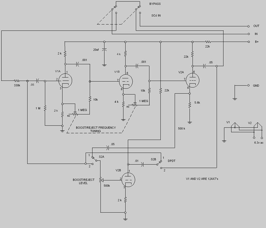
To gain some additional selectivity I built in a two-stage regenerative audio filter which can peak and reject any signal in the bandpass. I used a slightly modified version of the circuit found in the 1964 ARRL Handbook, “The Selectoject”. This also happens to be the name of a National Radio Company accessory called a Selectoject that was designed for use with the HRO-50 and -60 and the NC-173 and -183. The circuits are very similar, using the same tubes (2 x 12AX7).
Figure 3. Selectoject
After completing the receiver and testing it I was amazed at how much performance can be had with such a simple circuit. With a little practice, copying SSB and CW are a breeze. I also found that by putting the receiver into regeneration and zerobeating the carrier, the result is a “poor man’s” synchronous detection. Selective fade distortion disappears!
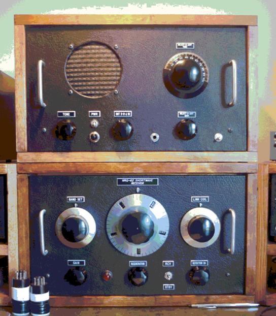
The upper cabinet houses the power supply, audio output stage and “selectoject”. The vernier dial on the right is the tuning adjustment for the selectoject which covers the entire audio range allowing peaking or nulling of any signal in the bandpass. Since the bandpass of a regenerative receiver is wide, this is a very handy circuit. The control below the vernier is the select/reject level control. The center control is the selectoject in/out switch. The knob on the left is the audio tone control. The switch is power on/off control which operates the pilot light below it also. I ran the pilot lights off of the 5 vac winding of the power transformer which was unused (I use solid state rectifiers). I also put a 10k resistor in series with the pilot lamps – I prefer muted pilot lights.
The lower cabinet houses the detector and two-stage audio preamplifier. Main tuning is via the large HRO-style dial. The vernier on the left is the bandspread tuning while the vernier on the right raises and lowers the antenna link coil over the cold end (top) of the detector coil. The control on the lower right is the audio gain control, center is the regeneration control (capacitor) and the control on the right is the detector B+ adjustment with also doubles as an SSB “clarifier”. The toggle switch is the Standby-Receive control which also extinguishes the pilot light on the panel.
Because I’m inept at with spray painting, I elected to cover the front panels with leather, a much more durable surface than any paint job I’ve ever done - and it’s attractive . . . once you get used to the idea. I put the leather on as the very last step, gluing it in place with Scotch 33 spray adhesive and use a new blade in my Exacto pen-knife to cut out all the holes for the controls.
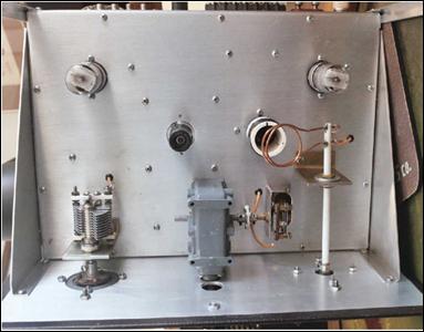
Figure 5. Detector and audio preamp chassis. Top and bottom views. Dead simple.
The original design called for placement of the bandset tuning (on the left) and bandspread tuning on the PW dial in the center. I built mine that way initially but have swapped the bandset (140pf) cap and the bandspread (15pf) cap so that the PW dial is the main tuning dial and the velvet vernier (on the left) is the bandspread or fine tuning dial. I prefer this arrangement for SWL’ing; however, the original configuration works better for hamband use. I find that the detector B+ pot makes a very effective super-fine tuning adjustment for SSB reception. I set it to 9 o’clock and adjust CCW or CW to act as a “clarifier”.
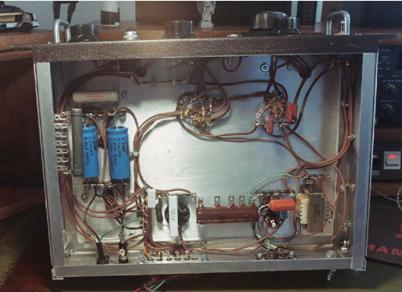
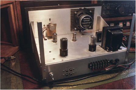
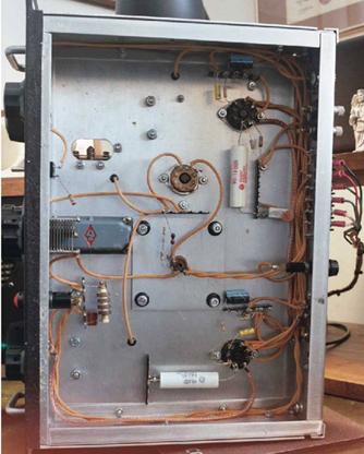
Figure 6. Power supply and audio output chassis.
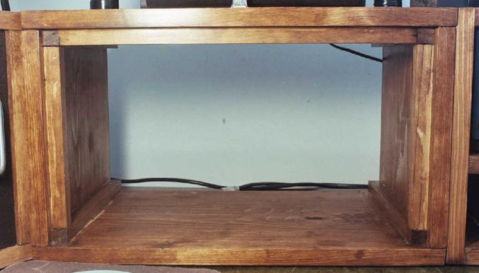
I built the cabinets from 1” finish grade pine boards 12 inches wide and 1x1’s to bolster the corners and act as “backstops” for the front panel. I didn’t mount the chassis to the cabinets. This way I can readily slide each chassis in and out – needed for coil changes.
Figure 7. Cabinet construction
So, what did I name my receiver? The NRQ-62, Bruce Vaughan built 59 regen receivers prior to his Ultimate Regenerative Receiver, #60. Then he built a second one to verify the design, #61. So I numbered mine #62, partially incorporating his callsign, NR5Q, I dubbed mine the NRQ-62.
The NRQ-62 is just so much more fun to operate, it became my main SWL set. Every new “catch” is a thrill. One evening I rewound one of my coils to add coverage of 60 meters. While tuning around 4.8 MHz I tuned in Radio Mauritanie on the west coast of Africa! Was I ever stoked! A couple of nights later, I wound a coil with 100 turns, thinking that ought to come out somewhere in the AM broadcast band. It worked! And the first station I tuned in was airing a radio play starring Lionel Barrymore. Is that cool, or what? The station was AM 780, ”Retro Radio for the Shenandoah Valley”.
Coverage for that coil turned out to be 760 kcs to 1470 kcs. I plan to add 10-20 turns to bring it down to 530 kc at the bottom end and wind a second coil to start around 1200 or 1300 kcs and run up above 160 meters. I am continuing to have lots of fun with this radio.
Well, that’s my Ultimate Regenerative Receiver in a nutshell. Do get hold of the three volumes of ER and read Bruce’s construction article. Also see earlier issues for other articles by Bruce Vaughan (the Ultimate Regen wasn’t his first article on regen’s he’s built).
In about 2007 Jim posted a message on one of the email reflectors
saying he was moving and needed to find a new home for his Ultimate Regen receiver. I quickly posted a reply saying I would be glad to give it
a home in my Radio Heaven museum.
About a week went by and I hadn't heard anything so I figured I had
missed it. Then I got an email from Jim saying he had had several folks
offer to take it, but he decided that this would be a good home for it.
Jim lives a long way off in northern VA so I wondered how I would go about getting it home. I posted a message on the email reflector asking if
anyone was going to be in that area who could pick it up for me.
My friend John W4AWM said he was going to a hamfest up there soon
and would get it for me and bring it to me at the Shelby hamfest coming
up in a couple of months.
So after several months the NRQ-62 arrived at it's new home.
It is a really great working receiver, I was surprised at how well it receives SSB.
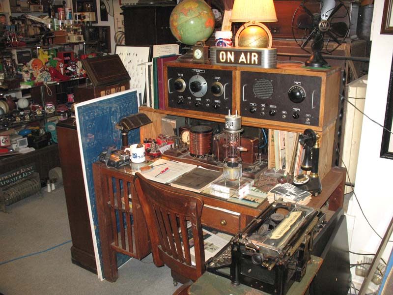
Here's a photo of the NRQ-62 on the desk in my
display room.
73, Ron w4ron
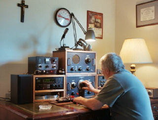

Jim K4XAF at the controls of the NRQ-62